
Start of a new Burner Design
Posted: November 3, 2014 Filed under: Burner, Homemade Boiler | Tags: Arduino boiler control, boiler, Burn test, burner, homemade chip boiler 1 Comment A friend with Solidworks has offered to draw up a new burner, so I thought I would post a few pictures of the old burner to help with dimensions. Here’s a picture of the uncleaned burner with about two inches of ash build up in the bottom of the burner.
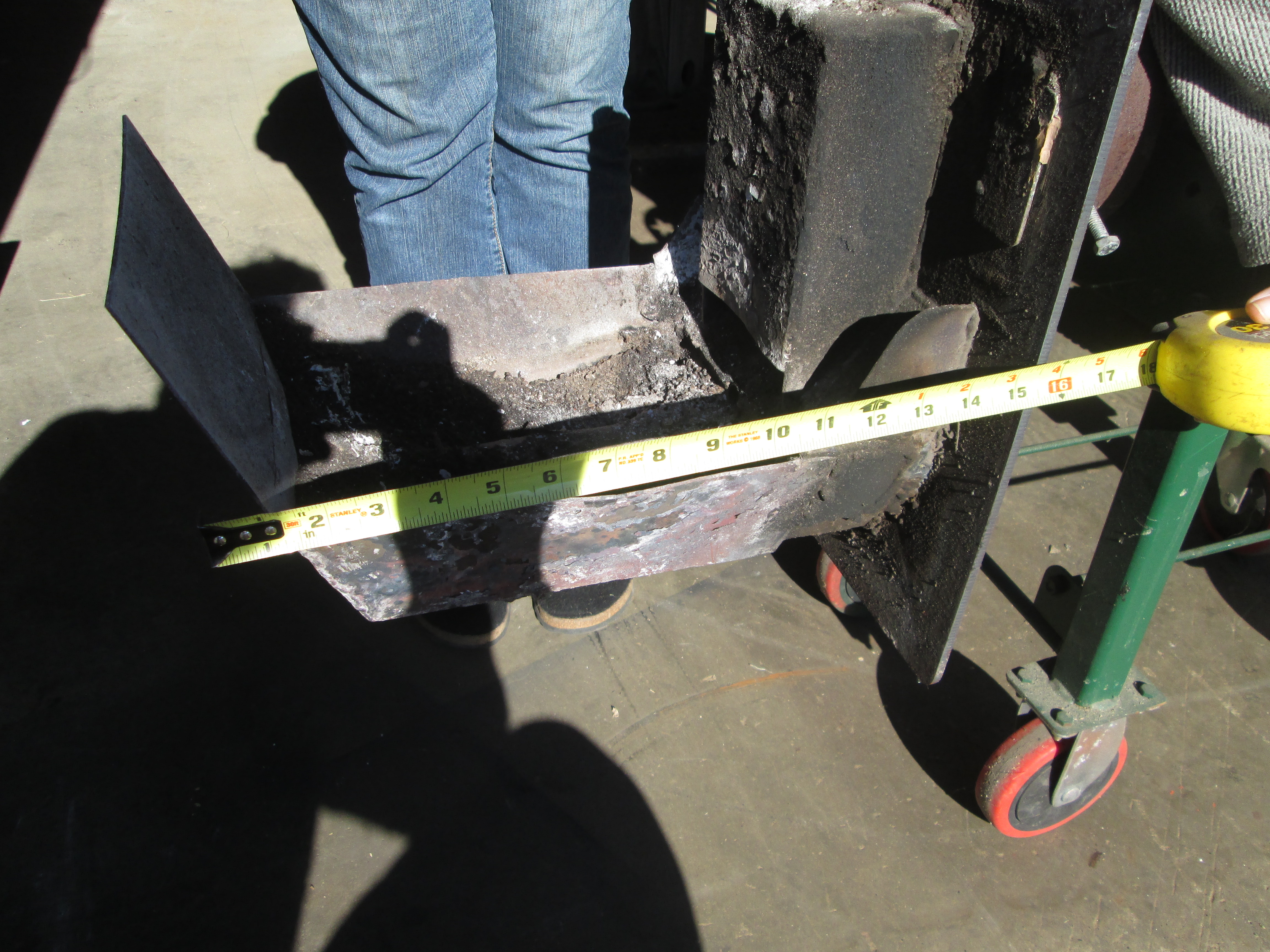
Side view uncleaned burner with tape
The tape measure in this view gives a little help with size. Originally the back flap was designed to help with air flow a sort of chimney effect, however this was of limited help and probably helped trap ash as do the high sides.

Top view showing hole size
The larger holes are 1/2″ and the ash still doesn’t fall through unless stirred.
Adding the Auger. Step two of a DIY record.
Posted: November 11, 2012 Filed under: Homemade Boiler, Hopper and Feed | Tags: auger feed, boiler, homemade chip boiler, welding Leave a commentIt may seem like a small bite but step two actually requires some machining and tweaking to get correct. In this step I am going to add the auger to the pipe assembly I have already built. To do this I need to support the auger with bearings so the shaft will be cantilevered in the pipe. The auger should not touch the pipe and needs to be centered in the pipe, at least within a reasonable distance. To do this I cut some 1 x 2 square tubing and then drilled holes on the Bridgeport using the Digital Readout to measure the distance so that the bearings would fit perfectly. These particular bearings are an oil impregnated bronze bushing in a pillow block configuration. The pillow block configuration is aluminum which makes machining the pillow block easy. Here’s a picture of the key way which I machined into a piece of 1″ cold rolled. If you have the choice cold rolled is much easier to work with then hot rolled for shafts. Of course this is really not shaft stock it is round stock but it works just fine and is inexpensive.

Shaft with key way machined and auger ready to weld onto shaft
After welding the auger onto the shaft I do the calculations to center the shaft in the pipe. To make the shaft centered I have to mill some of the pillow block bearing, as you can see in the picture I had to use a circular shim to get the auger centered in the pipe.

End view showing the machine pillow block bearings mounted onto 1 x 2 square tubing
Finally after some adjustment you can see the end result of the auger centered in the feed pipe.

Auger centered in pipe, cantilevered with two pillow block bearings
Changed feed sprocket
Posted: January 4, 2012 Filed under: Arduino, Homemade Boiler, Hopper and Feed, LCD display | Tags: Arduino, Arduino boiler control, auger feed, Auger motor, boiler, lcd display, LCD problems, pellets, relays, run time, shaded pole motor Leave a commentThe New Year practically demands resolutions and change for the better. So with that constant improvement theme in mind I am publicly stating my goal to lose 15#’s and so I am starting from 195.7. My second resolution is the constant improvement of the boiler. So here we go……
Auger feeding failure due to the motor stalling demanded the sprocket change on the auger motor feed assembly. The sprocket I chose doubles the torque available for feeding pellets. Since the shaded pole motor is constant speed the program had to change to double the auger run time. So taking the data I had gathered I changed the program in two ways.

New sprocket added
I changed the times to accommodate the speed change demanded by the sprocket change and I changed the paradigm to have constant run time and vary the dwell or off time. The increased torque is a vast improvement and since the change it has had no problem feeding even adding an entire bag of pellets at one time.
A second advantage of the change is the improvement of the LCD display. I think that this problem is now fixed since the LCD has been running without garbling the characters for several hours, long past the time when the LCD would normally have failed. By increasing the torque the auger feed motor is running at less amp draw and so it feeds back less to the relays. I also grounded the relay in a more positive way.

First Burn as a boiler
Posted: December 5, 2011 Filed under: Arduino, Homemade Boiler, Hopper and Feed | Tags: Arduino, boiler, prototype, test burn 1 Comment
Prototype burn mode
Limited success, the temperature in the tank did rise quickly and peaked at approx. 90°F before I shut the boiler feed off. The water in the boiler started at 56°F. The boiler smoked excessively and I think the top exhaust fan needs to be more robust. At present the bottom draft feed fans are approx. 1/3 more cfm than the top fan. To induce some negative pressure and reduce the smoking issues the top fan needs to increase. The other issue is the auger feed. The motor had a few issues with binding, The motor may have to be more powerful as well. I will take apart the feed tomorrow and hopefully determine where it was binding up. With luck there was a misaligned bearing or some other explanation. Otherwise I am a little at a loss. Over the weekend the piping got run with help. I mounted the 3/4″ copper on Unistrut this connected to the oil fired hot water boiler. A nice neat job if I say so myself. The 4″ .125 wall tube I used for an exhaust pipe seemed to work fine and stay cool in the 1/2 hour I ran the boiler. I still had some issues with the LCD screen however I am now convinced that this problem will fix it self with a separate power supply for the relays.
I wrote a very simple program this morning for the boiler control. No frills at all, and there were minor LCD issues. I think the LCD is very susceptible to voltage fluctuations. I will test this theory tomorrow as well.
